As electric vehicle production scales, the need to improve battery pack welding yields continues to increase. This is because battery modules and trays can contain hundreds of cells, each requiring multiple welds. At these volumes, even small defect levels can result in unacceptable failure rates and substantial resources lost to scrap and rework.
Many manufacturers still rely on traditional laser weld monitoring (LWM) tools to ensure quality. But these systems often don’t measure the weld directly or even accurately. This introduces uncertainty into the quality assurance process that leads to higher scrap rates while still inevitably failing to prevent bad products from going out the door.
To address this problem and continually advance the world’s battery manufacturing capabilities, IPG Photonics has combined on-the-fly (OTF) welding with our own, patented, real-time, inline laser weld measurement system. Used together, these technologies deliver the speed required for cost-effective, high-throughput battery production, as well as the measurement capabilities needed for accurate weld validation. This integrated approach enables higher yield, lower scrap, and greater confidence in weld integrity without slowing down the process.
Let’s explore some of the considerations, drivers, and challenges behind the development of this powerful battery welding solution.
Small Welds Have Big Consequences
Welds are required at virtually every phase of battery production – in cell manufacturing, when making cell-to-cell and cell-to-busbar connections, during module and pack integration, and even for fabricating structural enclosures. Laser beam welding (LBW) has already proven a versatile and cost-effective tool for making many of these welds.
In the later phases of battery production, LBW is usually accomplished via keyhole welding, rather than conduction welding. This is because keyhole welding offers deeper penetration, lower heat input, higher coupling efficiencies, and smaller heat affected zones (HAZs) than conduction welding. These characteristics better suit the needs of these applications.
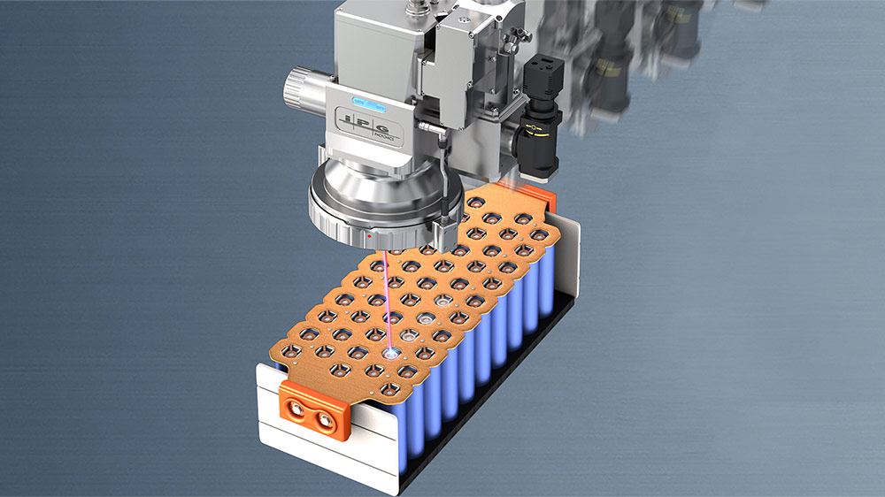
Keyhole LBW of battery connections – especially when connecting individual cell terminals to a collector plate or busbar – is a particularly critical production step.
Cell-to-busbar connections usually involve thin materials less than 1 mm thick. This makes the welding process highly sensitive to both under- and over-penetration. Specifically, under-penetration can yield a contact with poor conductivity, and over-penetration can damage the cell, possibly leading to catastrophic failure. Thus, poor welds have a big impact on product quality.
Another issue is that modules typically require hundreds of welds (at least two for each battery, multiplied by tens or hundreds of batteries per pack). This means that a defect rate as low as 1 in 10,000 can result in frequent failures at the module or battery level.
Compounding the risk, collector plate welding happens late in the manufacturing process after significant value has already been built into the battery. As a result, failure at this stage often means scrapping a fully assembled, high-cost component – or at least reworking it. This makes accurate, timely weld validation essential not just for quality, but for operational and economic viability.
Limitations of Traditional Laser Weld Monitoring
None of this is news to battery manufacturers, and they have long employed a variety of tools to ensure the quality of laser welds. Some of these LWM techniques include optical emission spectroscopy (OES), acoustic/ultrasonic monitoring, infrared (IR) and thermal imaging, and various other white light vision systems.
The problem with all these methods is that they don’t directly measure the one parameter that is of most critical interest – penetration depth. Traditionally, the only accurate measurement method requires a finished part to be cut open to view the weld cross section. While that can be quite instructive, it’s a destructive test that’s not widely applicable during production.
Instead, manufacturers must take data acquired by one of more of these LWM techniques and then compare them to ideal weld reference standards using statistical means. However, this reliance on pre-existing datasets is inherently limited by the assumptions it contains. If there are even subtle changes in the process – such as variances in incoming assemblies – the derived results may be incorrect. Worst of all, many methods cannot positively identify over-penetration and often end up reporting a substantial percentage of false failures.
The limitations of these LWM tools are a key reason why scrap rates remain stubbornly high for battery welding. The problem has even driven some manufacturers to design battery modules that are replaceable to compensate. But, in a world where EV makers are moving toward frame-integrated battery packs that’s not always an optimal strategy.
Getting Real (Weld Measurements)
Inline coherent imaging (ICI) was developed specifically to address the limitations of legacy LWM techniques. This technology was invented and patented (in North America) by Laser Depth Dynamics, now part of IPG Photonics. We call our ICI-based direct laser weld measurement technology LDD.
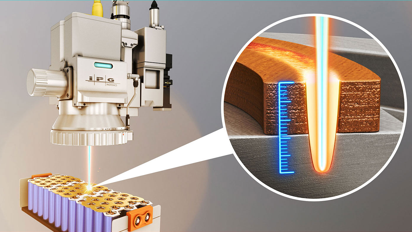
LDD uses a low power, near infrared measurement beam directed through the same optics as the welding beam. Because the LDD beam is coaxial with the welding beam, the measurement and process beams hit the workpiece in proximity. Acting like a mirror, the metal work piece reflects some of the LDD light back into the optics. This returned light is used to accurately measure the distance to the reflecting surface through interferometry.
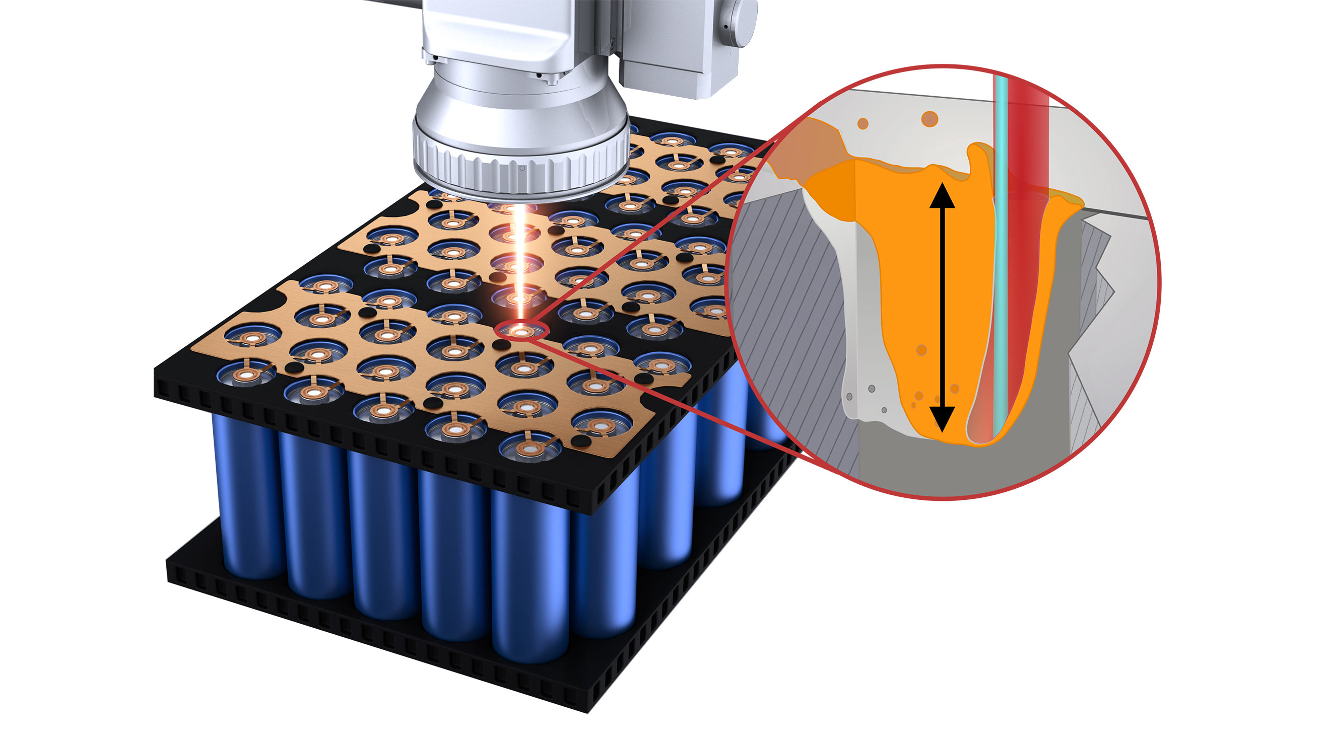
During keyhole LBW, the LDD beam is directed into that cavity and reflects off its bottom. This permits direct measurement of the keyhole depth, typically to an accuracy of within a few microns. Importantly, LDD is even capable of measuring the narrow, high aspect ratio keyholes produced by single mode lasers. All this distinguishes LDD from other weld monitoring methods that utilize a proxy signal – like heat, welding plume, or sound – and then attempt to approximate what is actually happening in the weld zone.

The LDD optics themselves also contain a galvo scanner which can rapidly move the measurement beam independent of the process beam. For typical inline weld measuring applications, the LDD beam is set to slightly trail the process beam and continuously monitor keyhole depth. But it may also be directed to the top surface of the work piece to maintain a depth reference.
Scanning the LDD measurement beam allows it to measure other important weld parameters besides keyhole depth. These include material height, seam position, finished (longitudinal) weld seam height, and transverse weld profile.
As a result, LDD enables manufacturers to transition from statistical monitoring to direct measurement. It provides the ability to validate every single weld individually, in real time.
This can have a huge cost and quality impact as has been demonstrated by many battery manufacturers already using LDD technology. Underpenetrated welds are identified as soon as they occur and can be flagged for immediate or subsequent rework. Welds with overpenetration can be noted. Thus, the problem of false scrap is virtually eliminated. It allows the manufacturer to decide if the part should be passed or scrapped right away – before further value is built into it.
Combining OTF + LDD: Speed Meets Quality
On-the-fly (OTF) LBW is another important technological milestone that has already delivered manufacturers with substantial benefits. In OTF LBW, the beam movements produced by the laser scanning system are tightly synchronized with actual part motion.
OTF significantly reduces how often the scanning system must come to a stop which greatly increases process speeds. Furthermore, it lets the scanning system mostly operate at the center of its field-of-view. This is advantageous because it minimizes optical distortions in the focused beam to produce more reliable welds.
The bottom line benefits of OTF welding are increased efficiency, higher throughput, enhanced precision, better reliability, and greater operational flexibility. OTF is also compatible with other beneficial LBW technologies like dual-beam lasers.
But OTF alone is only half the solution for high-throughput LBW of battery modules. Specifically, OTF improves speed, but still doesn’t necessarily ensure weld quality. That’s where LDD comes in.
Using OTF+LDD together, manufacturers no longer have to trade speed for quality. LDD complements OTF by verifying weld depth in real time, at full process speed. It also enables rework strategies. Under-penetrated welds can be flagged and corrected, while over-penetration events can be tracked as needed. The result is a process that’s faster, more reliable, and more controllable. And that translates directly into better yield, lower scrap, and more predictable production outcomes.
Engineering a Solution
While combining LDD and OTF offers obvious advantages, building a practical, reliable system that integrates these two technologies was a challenging task. One major issue is that the alignment between the measurement and welding beams must be maintained to within about within 5 µm.
The problem here is that the welding beam continuously changes direction. For example, if the final weld is a simple circular path, a traditional (fixed) welding scanner only needs to trace out that circle. But in OTF, the part or optics are in continuous motion, meaning the beam must follow a more complex path to compensate. And this complex path must be calculated in real time.
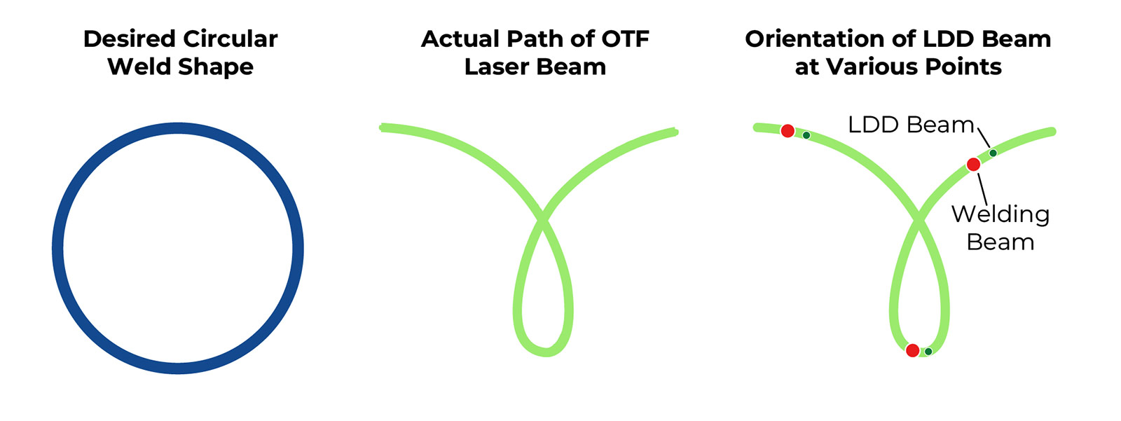
On top of that, the LDD beam must stay positioned just behind the welding beam inside the keyhole. But since the direction of beam travel keeps changing, the orientation of what constitutes “behind” also changes constantly. The LDD system must calculate all this in real time as the beam travels over the part surface at speeds of up to 1 meter per second.
Making LDD work together with OTF at production speeds was not something that could be accomplished with off-the-shelf components and a few tweaks to software. It required a deep understanding of optical, motion control, and beam delivery components as well as thermal dynamics and tooling.
IPG was uniquely positioned to engineer this solution because we design and manufacture the full tech stack for this system in house. We produce fiber lasers, of course, but also scanning heads, motion systems, control software, and the LDD system itself. We also build and integrate these components and technologies into many of our turnkey and custom sub-systems, full systems, and production lines.
This vertical integration gives us two key advantages when developing unique laser solutions. First, we have the experience required to completely understand and characterize problems before we identify solutions. Second, we have the development resources and engineering control over all the system components necessary to effectively implement them.
With these capabilities, IPG designers were able to develop a solution which acquires high-quality LDD data at production speeds, and which synchronizes beam steering at the level of precision required for OTF + LDD to function reliably on the line. We also developed the calibration routines, correction algorithms, and support tools necessary to maintain that precision over time despite heat, vibration, contamination, and wear.
But even that’s not enough. In production environments, performance depends just as much on what’s around the laser system as what’s inside it. That’s why we also supply fixturing, clamping, and tooling.
For example, collector plates don’t always sit perfectly flush with cell terminals. Busbars aren’t always rigid. The gap between two parts may vary slightly from weld to weld. That’s reality, and our systems have been designed to accommodate it. Whether it’s spring-loaded tooling to ensure consistent contact, gantry systems with micron level repeatability, or automatic beam alignment procedures to compensate for thermal drift, we build complete solutions, not just components.
Getting Started with a Laser Solution
IPG technologies like on-the-fly welding and real-time laser weld measurement are key components used in high productivity laser welding solutions. Interested in learning more about an IPG laser solution can benefit your operation?
Getting started is easy – send us some sample parts, visit one of our global application labs, or just tell us about your application.